
Equipment Management Department, Sinopec Yizheng Chemical Fiber Co., Ltd. 211900
Abstract : This paper analyzes the abnormal causes of large turbo expander units, puts forward a series of measures to solve the problems, and grasps the risk points and preventive measures of operation . Through the application of varnish removal technology, potential hidden dangers are eliminated and the intrinsic safety of the unit is ensured.
1. overview
The air compressor unit of the 60 t/a PTA plant of Yizheng Chemical Fiber Co., Ltd. is equipped with equipment from Germany MAN Turbo. The unit is a three-in-one unit, in which the air compressor unit is a multi-shaft five-stage turbine unit, the condensing steam turbine is used as the main driving machine of the air compressor unit, and the turbo expander is used as the air compressor unit. Auxiliary drive machine. The turbo expander adopts high and low two-stage expansion, each has a suction port and an exhaust port, and the impeller adopts a three-way impeller (see Figure 1)
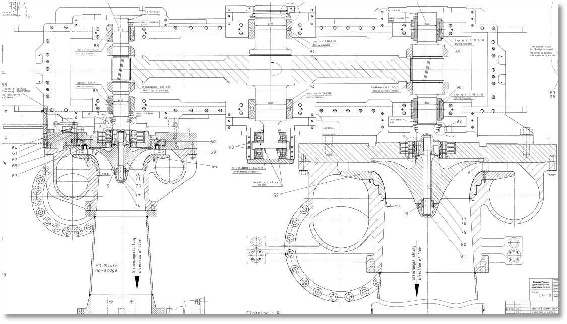
Figure 1 Sectional view of the expansion unit (left: high pressure side; right: low pressure side)
The main performance parameters of the turbo expander are as follows:
The high-pressure side speed is 16583 r/min, and the low-pressure side speed is 9045 r/min; the rated total power of the expander is 7990 KW, and the flow rate is 12700-150450-kg/h; the inlet pressure is 1.3Mpa, and the exhaust pressure is 0.003Mpa. The intake temperature of the high-pressure side is 175°C, and the exhaust temperature is 80°C; the intake temperature of the low-pressure side is 175°C, and the exhaust temperature is 45°C; a set of tilting pads are used at both ends of the high-pressure and low-pressure side gear shafts Bearings, each with 5 pads, the oil inlet pipeline can enter oil in two ways, and each bearing has one oil inlet hole, through 3 groups of 15 oil injection nozzles, the diameter of the oil inlet nozzle is 1.8mm, There are 9 oil return holes for the bearing, and under normal circumstances, 5 ports and 4 blocks are used. This three-in-one unit adopts the forced lubrication method of centralized oil supply from the lubricating oil station.
2. Problems with the crew
In 2018, in order to meet the VOC emission requirements, a new VOC unit was added to the device to treat the tail gas of the oxidation reactor, and the treated tail gas was still injected into the expander. Because the bromide salt in the original tail gas is oxidized at high temperature, there are bromide ions. In order to prevent the bromide ions from condensing and separating out when the tail gas expands and works in the expander, it will cause pitting corrosion to the expander and subsequent equipment. Therefore, it is necessary to increase the expansion unit. Intake temperature and exhaust temperature of high pressure side and low pressure side (see Table 1).
Table 1 List of operating temperatures at the inlet and outlet of the expander before and after VOC transformation
|
NO. |
Parameter change |
Transformation of the former |
After transformation |
|
1 |
High pressure side intake air temperature |
175 °C |
190 °C |
|
2 |
High pressure side exhaust temperature |
80 ℃ |
85 °C |
|
3 |
Low pressure side intake air temperature |
175 °C |
195 °C |
|
4 |
Low pressure side exhaust temperature |
45 °C |
65 °C |
Before the VOC transformation, the temperature of the non-impeller side bearing at the low pressure end has been stable at about 80°C (the alarm temperature of the bearing here is 110°C, and the high temperature is 120°C). After the VOC transformation was started on January 6, 2019, the temperature of the non-impeller side bearing at the low pressure end of the expander rose slowly, and the highest temperature was close to the highest reported temperature of 120°C, but the vibration parameters did not change significantly during this period (see Figure 2).
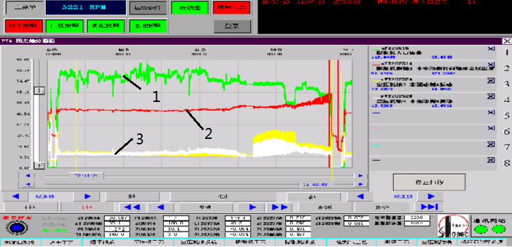
Fig. 2 Diagram of expander flow rate and non-drive side shaft vibration and temperature
1 – flow line 2 – non-drive end line 3 – non-drive shaft vibration line
3. Cause analysis and treatment method
After checking and analyzing the temperature fluctuation trend of steam turbine bearings, and eliminating the problems of on-site instrument display, process fluctuations, static transmission of steam turbine brush wear, equipment speed fluctuations, and parts quality, the main reasons for bearing temperature fluctuations are:
3.1 Reasons for the temperature rise of the non-impeller side bearing at the low pressure end of the expander
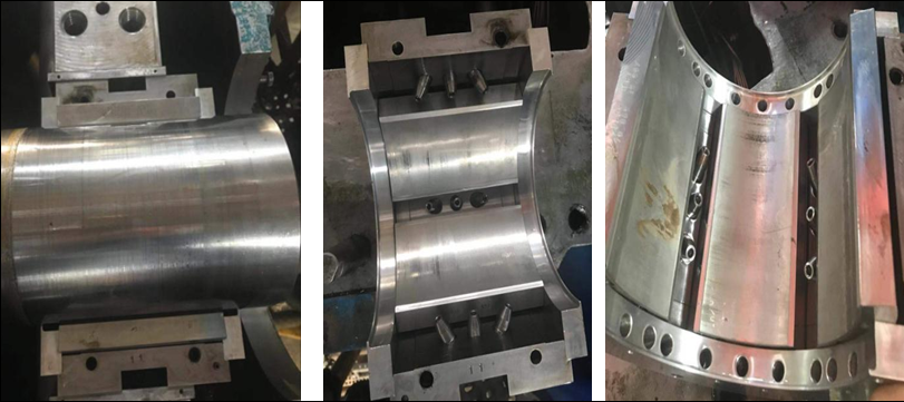
3.1.1 The disassembly inspection found that the distance between the bearing and the shaft and the meshing clearance of the gear teeth were normal. Except for the suspected varnish on the non-impeller side bearing surface at the low pressure end of the expander (see Figure 3), no abnormalities were found in other bearings .
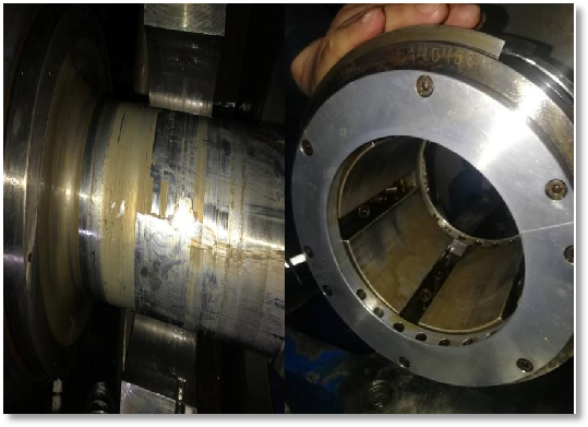
Figure 3 Physical picture of the non-drive end bearing and kinematic pair of the expander
3.1.2 Since the lubricating oil has been replaced for less than a year, the quality of the oil has passed the test before driving. In order to eliminate doubts, the company sent the lubricating oil to a professional company for testing and analysis. The professional company confirms that the attachment on the bearing surface is an early varnish, MPC ( varnish propensity index ) (see Figure 4)
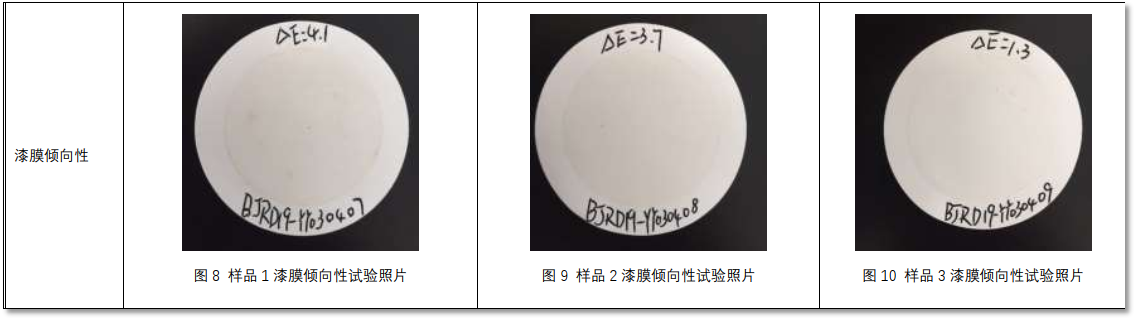
Figure 4 Oil monitoring technology analysis report issued by oil monitoring professional technology
3.1.3 The lubricating oil used in the expander is Shell Turbo No. 46 turbine oil (mineral oil). When the mineral oil is at a high temperature, the lubricating oil is oxidized, and the oxidation products gather on the surface of the bearing bush to form a varnish. Mineral lubricating oil is mainly composed of hydrocarbon substances, which are relatively stable at room temperature and low temperature. However, if some (even a very small number) of hydrocarbon molecules undergo oxidation reactions at high temperatures, other hydrocarbon molecules will also undergo chain reactions, which is a characteristic of hydrocarbon chain reactions.
3.1.4 The equipment technicians conducted investigations around the support of the equipment body, the cold stress of the inlet and outlet pipelines, the leak detection of the oil system, and the integrity of the temperature probe. And replaced a set of bearings at the non-drive end of the low-pressure side of the expander, but after driving for a month, the temperature still reached 110 ℃ , and then there were large fluctuations in vibration and temperature. Several adjustments were made in order to get close to the pre-retrofit conditions, but almost without any effect (see Figure 5).
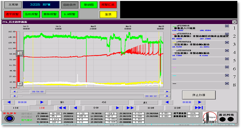
Figure 5 Trend chart of related indicators from February 13 to March 29
the MAN Turbo manufacturer, under the current working conditions of the expander, if the intake air volume is stable at 120 t/h , the output power is 8000kw, which is relatively close to the original design output power of 7990kw under normal working conditions; When the air volume is 1 30 t/h , the output power is 8680kw; if the intake air volume is 1 46 t/h , the output power is 9660kw. Since the work done by the low-pressure side accounts for two-thirds of the expander, the low-pressure side of the expander may be overloaded. When the temperature exceeds 110 °C , the vibration value changes drastically, indicating that the newly formed varnish on the surface of the shaft and the bearing bush is scratched during this period (see Figure 6).
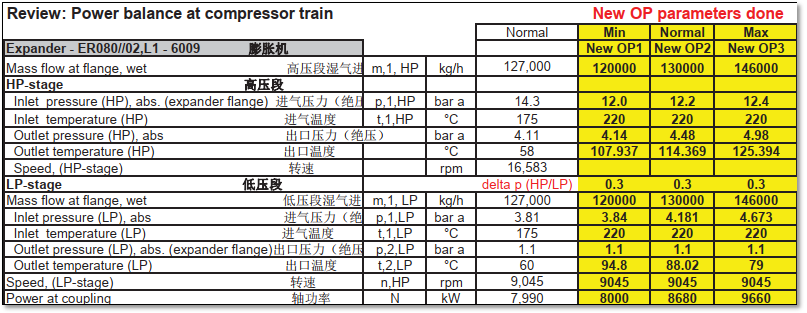
Figure 6 Power balance table of expansion unit
3.2 Mechanism Analysis of Existing Problems
3.2.1 As shown in Figure 7, it can be seen that the included angle between the slight vibration direction of the fulcrum of the tile block and the horizontal coordinate line in the coordinate system is β , the swing angle of the tile block is φ , and the tilting pad bearing system composed of 5 tiles, when the tile When the pad is subjected to oil film pressure, since the fulcrum of the pad is not an absolute rigid body, the position of the fulcrum of the pad after compression deformation will produce a small displacement along the geometric preload direction due to the stiffness of the fulcrum, thereby changing the bearing clearance and oil film thickness [1 ] .
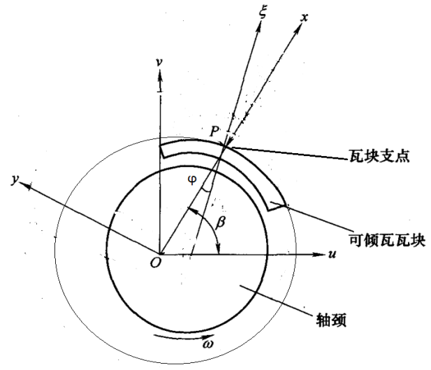
Fig.7 Coordinate system of single pad of tilting pad bearing
3.2.2 It can be seen from Figure 1 that the rotor is a cantilever beam structure, and the impeller is the main work component. Since the impeller side is the driving side, when the gas expands to do work, the rotating shaft on the impeller side is in an ideal state in the bearing bush due to the effect of gas damping, and the oil gap remains normal. In the process of meshing and transmitting torque between the large and small gears, with this as the fulcrum, the radial free movement of the non-impeller side shaft will be limited under overload conditions, and its lubricating film pressure is higher than that of other bearings, making this place lubricated The film stiffness increases, the oil film renewal rate decreases, and the frictional heat increases, resulting in a varnish.
3.2.3 The varnish in the oil is mainly produced in three forms: oil oxidation, oil “micro-combustion”, and local high-temperature discharge. The varnish should be caused by the “micro-combustion” of the oil. The mechanism is as follows: a certain amount of air (generally less than 8% ) will be dissolved in the lubricating oil. When the solubility limit is exceeded, the air entering the oil will exist in the oil in the form of suspended bubbles. After entering the bearing, the high pressure causes these bubbles to undergo rapid adiabatic compression, and the fluid temperature rises rapidly to cause adiabatic “micro-combustion” of the oil, resulting in extremely small-sized insolubles. These insolubles are polar and tend to adhere to metal surfaces to form varnishs. The greater the pressure, the lower the solubility of the insoluble matter, and the easier it is to precipitate and settle to form a varnish.
3.2.4 With the formation of the varnish, the thickness of the oil film in the non-free state is occupied by the varnish, and at the same time the renewal speed of the oil film decreases, and the temperature rises gradually, which increases the friction between the surface of the bearing bush and the shaft, and the deposited varnish causes Poor heat dissipation and rising oil temperature lead to high bearing bush temperature . In the end, the journal rubs against the varnish, which is manifested in violent fluctuations in the shaft vibration.
3.2.5 Although the MPC value of the expander oil is not high, when there is a varnish in the lubricating oil system, the dissolution and precipitation of the varnish particles in the oil is limited due to the limited ability of the lubricating oil to dissolve the varnish particles. It is a dynamic balance system. When it reaches a saturated state, the varnish will hang on the bearing or bearing pad, causing the temperature fluctuation of the bearing pad, which is a major hidden danger affecting safe operation. But because it adheres to the bearing pad, it is one of the reasons for the temperature rise of the bearing pad.
4 Measures and Countermeasures
Removing the accumulation of varnish on the bearing can ensure that the bearing of the unit runs at a controlled temperature. Through research and communication with many manufacturers of varnish removal equipment, we chose Kunshan Winsonda, which has good use effect and market reputation, to produce WVD-II electrostatic adsorption + resin adsorption, which is a compound varnish removal equipment to remove paint. membrane.
WVD-II series oil purifiers effectively combine electrostatic adsorption purification technology and ion exchange technology, solve the dissolved varnish through resin adsorption, and solve the precipitated varnish through electrostatic adsorption. This technology can minimize the content of sludge in a short time , In a short period of several days, the original lubrication system containing a large amount of sludge/varnish can be restored to the best operating state, and the problem of the slow rise in temperature of the thrust bearing caused by the varnish can be solved. It can effectively remove and prevent the soluble and non-soluble oil sludge generated during the normal operation of the steam turbine.
Its main principles are as follows:
4.1 Ion exchange resin to remove dissolved varnish
Ion exchange resin is mainly composed of two parts: polymer skeleton and ion exchange group. The adsorption principle is shown in Figure 8,
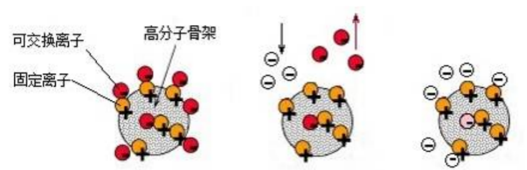
Figure 8 Principle of ion-interaction resin adsorption
The exchange group is divided into a fixed part and a movable part. The fixed part is bound on the polymer matrix and cannot move freely, and becomes a fixed ion; the movable part and the fixed part are combined by ionic bonds to become an exchangeable ion. The fixed ions and the mobile ions have opposite charges respectively. At the bearing bush, the mobile part decomposes into freely moving ions, which exchange with other degradation products with the same charge, so that they combine with the fixed ions and are firmly adsorbed on the exchange base. On the group, it is taken away by the oil, dissolved varnish removed by ion exchange resin adsorption.
4.2 Electrostatic adsorption technology to remove suspended varnish
Electrostatic adsorption technology mainly uses a high-voltage generator to generate a high-voltage electrostatic field to polarize the polluted particles in the oil to show positive and negative charges respectively. The neutral particles are squeezed and moved by the charged particles, and finally all the particles are adsorbed and attached to the collector (see Figure 9).
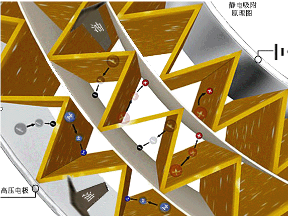
Figure 8 Principle of electrostatic adsorption technology
Electrostatic oil cleaning technology can remove all insoluble pollutants, including particulate impurities and suspended varnish produced by oil degradation . However, traditional filter elements can only remove large particles with corresponding precision , and it is difficult to remove submicron level suspended varnish .
This system can completely solve the varnish precipitated and deposited on the bearing pad, thereby completely solving the influence of the bearing pad temperature and vibration changes caused by the varnish, so that the unit can run stably for a long period of time .
5 Conclusion
WSD WVD-II varnish removal unit was put into use , through two years of operation observation, the bearing temperature has always been maintained at around 90°C, and the unit has remained in normal operation. A varnish film was found (see Figure 10) .
The physical picture of bearing disassembly after installing varnish removal
equipment
references:
[1] Liu Siyong, Xiao Zhonghui, Yan Zhiyong, and Chen Zhujie . Numerical simulation and experimental research on the dynamic characteristics of pivot elastic and damping tilting pad bearings [J]. Chinese Journal of Mechanical Engineering, October 2014, 50(19):88.
Post time: Dec-13-2022